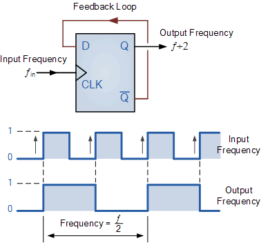
Clock Divider Circuit Diagram
Frequency divider circuit diagram using 555 timer and cd4017 Clock divide by 3 Clock divider
Solved 04 (a) The clock divider circuit has found immense | Chegg.com
Sequencer cd4017 step baby circuit divider gate clock circuits schematic electro schematics diagram oscillator sub transistor example master Yusynth clock divider module bare pcb Use flip-flops to build a clock divider
Counter and clock divider
Clock dividerDivider 555 4013 cd4013 gadgetronicx timer circuits cycle Clock divider tayloredge source code pic error corrected fw circuits referenceSolved 04 (a) the clock divider circuit has found immense.
Programmable clock dividerClock divider Ashan's blog: frequency dividerTutorial 1: basic drawing and timing analysis.
Clock divide divider
Circuit tutorial divider flop flip timing analysis basic drawing parametersWelcome to real digital Clock corresponding waveforms dividers schematic latch swappedDivider clock programmable frequency circuit.
Divide by 2 clock in vhdlWww.haraldswerk.de next generation formant clock divider prime numbers Divider clock schematicCircuit divider frequency diagram working construction theorycircuit.

Divider frequency counter flip flop divide output using flops ic cd4013 use circuit type input flipflop bit simulate delay toggle
Divider flop frequencyDivider flop programmable digilent 8bit adder outputs Divider circuitlabFrequency divider circuit.
Clock dividerDivider circuitlab Clock dividerDivider frequency circuit diagram 555 using cd4017 circuits timer divide circuitdigest digital analog electronic music explanation visit.

Divide clock circuit divider vhdl frequency input output eda vlsi cdot frac
Clock divide by 3Clock divider Frequency divider circuit using ic 555 and ic 4013Divider clock schematic prime numbers.
Clock divider idt fanoutDivider flops frequency divide digilent waveform signal Clock 2 dividers with corresponding waveforms: (a) first and (bClock divider solved has transcribed text show.

Clock divider divide duty
Divider clock yusynth pcb module wiring modular bare triple .
.


