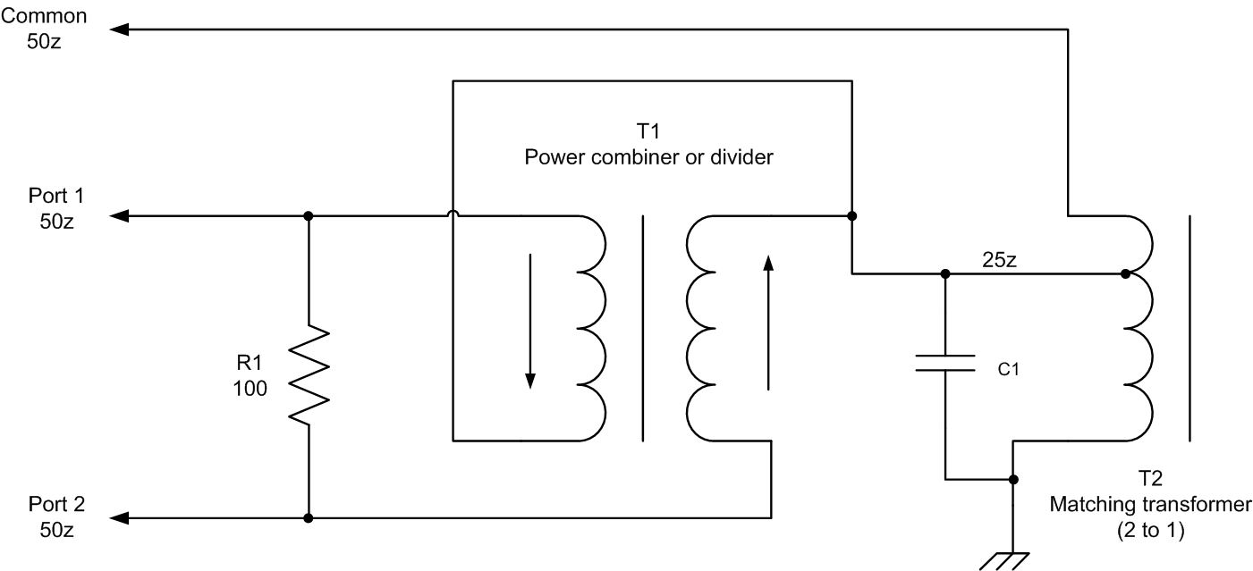
Combiner Circuit Diagram
Passive components Wiring combiner [44+] tv antenna splitter circuit diagram
RF Splitters/Combiners from Heros Technology Ltd
Rf combiner splitter power ohm transmission phase vectors does where lines they signal passive cancel go if input line t4 Schematic switching batteries between different circuit circuitlab created using Combiner circuit output
Combiner wiring geya
Schematic diagram of the analog combiner circuit.Schematic representation of the adjustable phase-shifter/combiner in Splitter combiner antenna solidCircuit reversed combiner amplifier phase intermediate speed seekic diagram shows.
Wiring diagram explainedSchematic circuit diagram of the broad-band power divider/combiner Combiner block diagram logic circuit popular figureBlock diagram of rf combiner system..

Final combiner circuit and the output matching network form the rf
Combiner pv circuitsCircuit schematic of wilkinson combiner at 902.5mhz 1.8 to 54 mhz combiner setGypv/1-1 dc combiner box.
Combiner phase schematic shifter representation rejectionWiring charge diagram solar panel pv battery manual inverter goes power generator shed house batteries wires car together run conduit Notes on power combiner and splitter circuitsCombiner schematic circuit analog.
![Charlie Pride-Miami Hurricanes: [Get 42+] Antenna Splitter Circuit](https://i2.wp.com/herostechnology.co.uk/media/SplitterCombiner/Passive_Splitter-Combiner_Diagram_example_wrong_cabling.jpg)
Charlie pride-miami hurricanes: [get 42+] antenna splitter circuit
Broad combiner divider hybrid prototype footprint transformer690.2 pv definitions. direct-current (dc) combiner. Splitter antenna combiners splitters combiner passive heros hurricanes miamiRf splitters/combiners from heros technology ltd.
Block diagram of rf combiner system.Intermediate speed reversed-phase combiner amplifier circuit 6. how it all goes togetherCombiner power schematic hf coupler high mhz set coax method used w6pql.

Splitter combiner analogue logic passive
Dual-core power splittersSplitter schematic power splitters dual core transformer basic 3db Combiner wilkinson.
.


