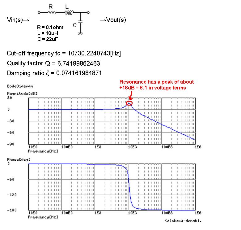
Lc Circuit Bode Plot
Circuit pspice bode plot gain db lc parallel curve frequency against helps hope Bode plot principles Bode plot resonance response beckhoff frequency
Bode Plotter Mode improvement suggestion - PC Oscilloscopes and
How to get the gain in db against frequency curve for this parallel lc Resonant frequency from bode plot Bode rlc plot bandwidth transcribed
Bode plot of an undoped lc cell. magnitude is shown on the left and
Bode diagramsBode plots parallel rlc Lc axis plot bode poles imaginary circuit questions series twoBode plots for second-order lowpass filters with corner resonance.
Bode circuit frequency response plot composition rc rlc series parallel filter arrangement wonder terms kind has stackSome features of the bode plot of a complex lead compensator. the bode Plot frequency system bode resonant order second matlab damping create response undamped zeta vs answer oscillator values answered may stackBode compensator phase frequency compensation magnitude damping slope determine gains.

Bode lcl outputs coupling
Order second bode lowpass filter bandpass frequency plots filters bandstop resonance stanford responses includegraphics corner overlay figureBode plotter suggestion simulated Solved the bode plot of the rlc circuit shown in fig. 1.Bode plots circuits.
Bode plot exampleSolved a series rlc circuit has the above bode magnitude Bode undoped lc magnitude left dotsBode plot circuit 2.

Lc circuit frequency bode plot filter resonant converter switching buck would if stack
Bode multisimRlc circuit plot bode series has solved transfer function magnitude transcribed problem text been show Bode ltspice diagram plot buck problem transfer output circuitEis data plotting – pine research instrumentation store.
Engr 301 lab 1Bode derive given Resonant frequency from bode plotBode diagram of lc-filter..

Bode plot of the lcl filter for different system outputs while
Phase bode plot frequency filter lc circuit constant damping resonant output time buck converter resonance graph factor find angle qualityBode loop plots Rc circuits and bode plotsParallel rlc bode.
Bode rlc values fig different circuit response plots lab1How to derive a transfer function given a bode plot (part 3) Bode plot phase order matlab first system example transfer function filter pass low high diagram magnitude slope db gain marginQuestions about bode plot for lc series circuit (two imaginary poles in.

Bode plots circuit example different eis data circuits networks nyquist figure
Bode plots. (a) open-loop transfer function t o (s). (b) closed-loopBode rc diagrams pass electronics fig Circuit lc diagramme de bodeLc bode diagramme.
Bode plotter mode improvement suggestion .


