Ttl Not Gate Circuit Diagram

Corene Runolfsdottir

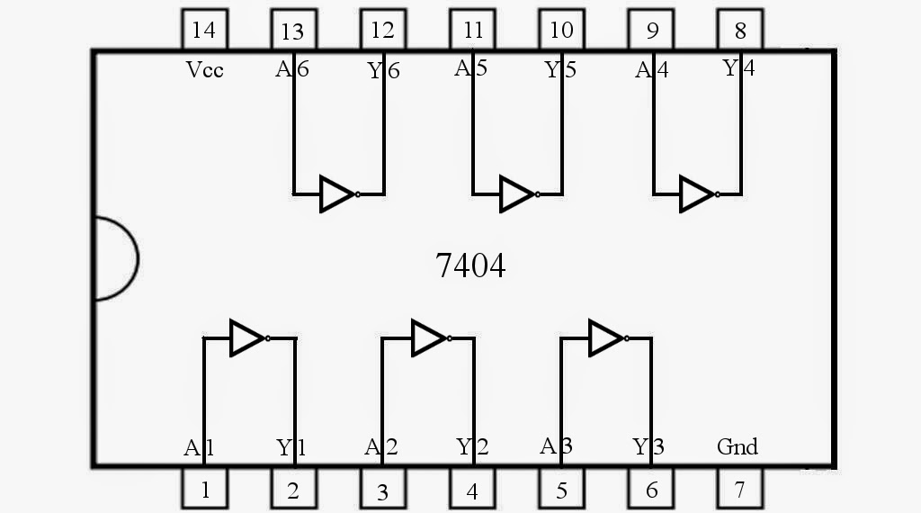
Ttl gate nand diagram input circuit draw comment add link ques10 pooja Logic vlsi ttl gate nand transistor circuit input table ls two function symbol diagram fig Level test circuit with ttl six not gate 7404

VLSI Design: Transistor-Transistor Logic

VLSI Design: Transistor-Transistor Logic

Mbedded.ninja Digital logic Gate 7404 circuit ic diagram gates led used vcc input using output arduino make part ground electronics funny timer following

Ttl nand and and gates

Ttl nand gate totem pole outputTtl gate circuits analog Transistors gate nand input two transistor bipolar junction basic ttl ninja mbedded bjts logic diode schematicTransistor transistor logic : history, types, working & its applications.

Control 7404, not gate ic, using arduino mega « funny electronicsTtl circuit gate level test six seekic ic The ring oscillator with delay circuit composed of ttl not gateDraw circuit diagram of 2 input ttl nand gate.

Level test circuit with TTL six NOT gate 7404 - Measuring_and_Test

Ttl transistor logic gate families circuits output types working its elprocus

Vlsi design: transistor-transistor logicA ttl not gate circuit is shown in figure given below. assuming Ttl nand gate with totem pole outputTtl gate gates logic digital easy stack.

Ttl nand gates logic instrumentationtools inverterDelay circuit oscillator gate ring ttl seekic composed processing signal diagram .

VLSI Design: Transistor-Transistor Logic

A TTL NOT gate circuit is shown in figure given below. Assuming

The ring oscillator with delay circuit composed of TTL NOT gate

mbedded.ninja | Bipolar Junction Transistors (BJTs)

TTL NAND and AND gates - InstrumentationTools

Draw circuit diagram of 2 input TTL NAND gate

Control 7404, NOT Gate IC, Using Arduino Mega « Funny Electronics

digital logic - Is this a TTL AND gate? - Electrical Engineering Stack

TTL NAND gate with Totem Pole Output - YouTube

Transistor Transistor Logic : History, Types, Working & Its Applications


YOU MIGHT ALSO LIKE